SwitchingNetwork
Draws a boolean expression as a switching (relay) network: a conjunction (&) becomes two sub-networks in series (current must pass through both), a disjunction (|) becomes two sub-networks in parallel (current can pass through either), and a variable — negated or not — becomes a single switch. Built from one expression string in a single-shot constructor:
SwitchingNetwork sn = SwitchingNetwork("(A & B) | (!A & C)");

Image img = Image();

img.width(10);

img.height(6);
img.padding(0.5);
img.caption_title("Figure");
img.caption_text("$(A \wedge B) \vee (\bar{A} \wedge C)$, a two-way multiplexer.");
img.add(sn);
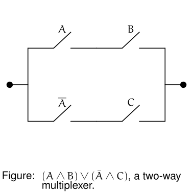
Open and closed switches
Every switch renders open by default — the diagonal tick that reads as a break in the wire. close(variable)/open(variable) set a specific atomic proposition’s state explicitly; calling either again for the same variable overrides its previous state.
SwitchingNetwork sn = SwitchingNetwork("(A & B) | (!A & C)");
sn.close("A");   // A's switch draws closed (an unbroken wire) -- and A's negation draws open
Setting a variable’s state affects both every switch for that variable and every switch for its negation, drawn as the opposite state — physically the two are wired to the same mechanism, so close("A") closes every A switch and opens every !A switch at the same time. variable must actually appear in the expression the network was built from.
Methods
| Method | Purpose |
|---|---|
SwitchingNetwork(expression) | Parse the expression and build the network |
close(string variable) | Draw every switch for variable closed, and every switch for its negation open |
open(string variable) | Draw every switch for variable open, and every switch for its negation closed |
set_debug_mode(bool) | Draw bounds |
Expression syntax
Programmer-style, not LaTeX — variables are plain identifiers, and operators are ASCII symbols:
| Symbol | Meaning | Precedence |
|---|---|---|
! | Negation | Tightest — binds before & and \| |
& | Conjunction (AND) | Binds before \| |
\| | Disjunction (OR) | Loosest |
( ) | Grouping | Overrides the above |
So A & B | C means (A & B) | C, and !A & B means (!A) & B — use parentheses whenever you mean something other than that. A negated variable is drawn with a bar over its label (e.g. !A renders as $\bar{A}$); the expression is converted to negation normal form internally (via De Morgan’s laws) before layout, so !(A & B) draws identically to !A | !B — a real switching network can only negate a single variable’s own switch, not an entire sub-network, so this conversion is what makes an expression like !(A & B) renderable at all.
The whole network is uniformly scaled (preserving its proportions, centered) to fit the given width/height, the same letterboxing approach Plot uses. A short lead wire extends from each side of the network out to a filled terminal dot labeled $T_1$ (input) and $T_2$ (output), marking its two overall connection points. Every individual switch marks its own pivot (where the blade is hinged) and connection point (the fixed contact it swings to meet when closed) with a smaller filled dot each, in the same spot whether the switch is open or closed. Wherever the circuit branches into a parallel (|) composition, or two branches recombine, that point gets a dot too, set back from its branches by a short inset lead wire on both sides — so a parallel composition always has some breathing room between its own branch/merge dots and whatever’s inside it, even when both branches are the same width. Two sub-networks placed in series (&) are joined by a short connecting wire rather than butted directly together, so each stays visually distinct. Row spacing, switch size, lead-wire length, series-gap length, parallel-inset length, and dot sizes are theme constants (switch_unit_width, switch_unit_height, switch_parallel_spacing, switch_parallel_lead, switch_series_gap, switch_tick_height, switch_lead_length, switch_terminal_radius, switch_pivot_radius, switch_thickness).